
Design Guide for 3D Printing
Guidelines, formats, and useful tips for designing your files
HOW TO ORDER
SHEET METAL DESIGN GUIDE
INVOICING AND PAYMENTS
SHIPMENTS
Printing with FDM
How is print density managed?
The parts to be printed in FDM are always evaluated by our technicians, the average final density ratio is approximately between 30-35%.
How much strength do FDM printed parts have?
It depends a lot on both the material selected and the print orientation.
Our technicians will orient the part, unless expressly requested by the customer, according to a good realization.
N.B. (obviously the part printed on the Z axis will have a lower load resistance)
How is FDM technology managed?
Projects in FDM technology will be managed as RFQs, so that we can evaluate your every request very carefully. After the evaluation of our technicians, you will receive our quote complete with all the details
Was this helpful? Make your quote now
Usable formats
We accept the most common file formats used in industrial design and manufacturing. In particular, we support:
- . STEP/. STP – Preferred format for CNC, sheet metal, stamping, and assembly machining: Allows for detailed technical analysis of the 3D model.
- . STL – Ideal for 3D printing, it is used for automatic quoting and direct production.
- . IGES/. IGS, . DXF, . DWG – Compatible to attach specifications of on-demand machining, such as sheet metal cutting.
- .PDF – Useful for attaching technical drawings, dimensional indications or additional notes.
It is always recommended to attach the 3D file in the native format that best suits the selected process, and include any technical specifications in the notes. In case of doubts or complex files, our technical team is available to support you in validating the project.
Was this helpful? Make your quote now
Ink Unit Dimensions and Tolerances
Nylon PA12
- Dimensions: 380x284x380
- Tolerance: ±0.50 mm and ± 0.50 % for 100mm size >
The above tolerances are valid both for measurements made on the entire part and on measurements made on parts of it (holes, pins, center distances…)
| Nominal: 0 - 30 mm | Nominal: 30 - 50 mm | Nominal: 50 - 80 mm | |||
|---|---|---|---|---|---|
| XY | Z | XY | Z | XY | Z |
| + 0.50 mm | + 1.10 mm | + 0.60 mm | + 1.40 mm | + 0.70 mm | + 1.80 mm |
For higher nominal values, the manufacturer (HP) does not provide specific indications for the high variability of the results.
It is the responsibility of the customer or even better of the designer of the file, to follow these indications for compliance and success of the work.
Was this helpful? Make your quote now
Thickness and thin wall size
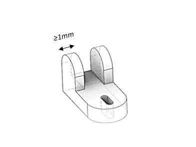
The MJF printing technique guarantees quality even to thinner parts or walls, taking into account, however, that their thickness must be at least greater than 1 mm to have feasibility and not incur any problems of fragility and/or unwanted deformations.
Was this helpful? Make your quote now
Limits of clearances and grafts
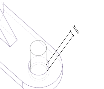
The parts that will have to be grafted, mated and/or intersected, will need at least 1 mm of clearance.
It is the responsibility of the customer or even better of the designer of the file, to follow these indications for compliance and success of the work.
Was this helpful? Make your quote now
Groove recommendations
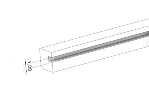
As for the grooves, a minimum spacing between parts of 1 mm is recommended, always taking into account the proportions with the height of the walls.
It is the responsibility of the customer or even better of the designer of the file, to follow these indications for compliance and success of the work.
Was this helpful? Make your quote now
Unloading material into large empty parts
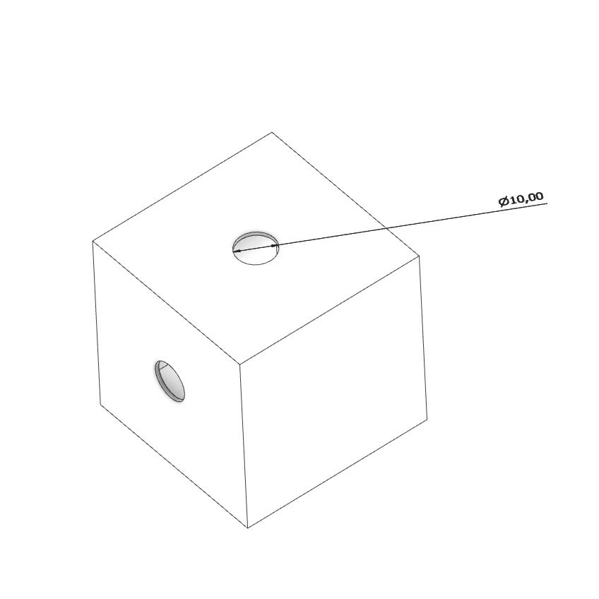
In large hollow parts, we recommend the design of two holes ≥ 10 mm diameter to ensure the dust escapes.
It is the responsibility of the customer or even better of the designer of the file, to follow these indications for compliance and success of the work.
Was this helpful? Make your quote now
Cavities, channels and coils
As for cleaning the material in small spaces such as cavities, channels, coils or simple holes, a diameter of at least 1mm is recommended. In the event that the depth is greater than three times the diameter, you will not be guaranteed total cleanliness of the hole or cavity. We also suggest adding through holes rather than blind ones, to facilitate the cleaning operation.
It is the responsibility of the customer or even better of the designer of the file, to follow these indications for compliance and success of the work.
Was this helpful? Make your quote now
Optimization of text and logo results
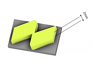
The thicknesses of texts and or logos (engraved or embossed), in order for them to be visible, must have a minimum size of 2mm.
Multi-part cages
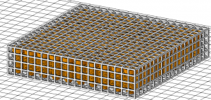
In order to be able to upload a file containing multiparts, of small dimensions equal or different from each other, it is possible to create a containment cage at least 1 mm thick, where the pieces must be at least 2/3 mm apart.
The cage must have sufficient spacing between the walls to allow the best possible cleaning, taking into account, however, that the smallest part inside does not come out.
Your project will be shipped to you inside the cage and for these reasons you are not guaranteed the total cleanliness of the parts inside it, without adequate quality control of the individual pieces and the lack of the possibility of any coloring.
Holes and threads
3D printing does not allow us to process standard threads, so we propose below
different types of holes to be able to make them in post-processing:
- Draw the hole with the diameter dimensions according to ISO standards, so that the thread can be made later with suitable tools. We recommend that you draw the hole smaller than ±0.2mm compared to the diameter, in order to compensate for any printing tolerance of ±0.50mm, so that you can shoot the hole with a drill bit.
- Draw the hole already threaded on a 3D model, and then you can resume it with a suitable tool for threading following the trace of the printed thread, this method is recommended especially for threads of sizes starting from M5-M6. Also in this case it is advisable to keep a negative tolerance of at least 0.1mm on the drawing with respect to the ISO dimensions.
- Another solution we recommend is to create a suitable seat in which to insert inserts
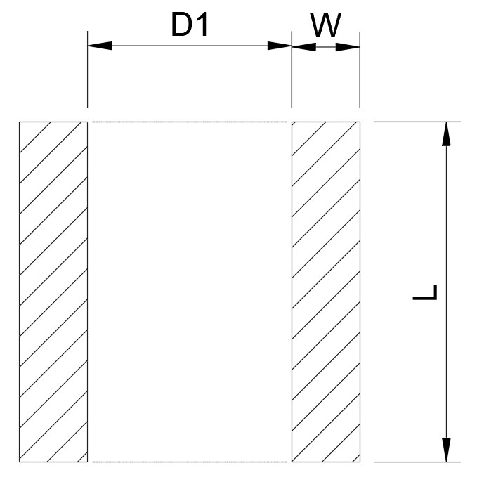
| Dimensions | ⌀ Q1 | L+(1mm) | W +(min.) |
|---|---|---|---|
| M3 | 4.0 mm | 5.7 mm | 1.6 mm |
| M4 | 5.6 mm | 6.35 mm | 2.1 mm |
| M5 | 6.4 mm | 9.5 mm | 2.6 mm |
| M6 | 8.0 mm | 12.7 mm | 3.3 mm |
| M8 | 9.5 mm | 12.7 mm | 4.5 mm |
It is the responsibility of the customer or even better of the designer of the file, to follow these indications for compliance and success of the work.
Was this helpful? Make your quote now