
Sheet Metal Design Guide
Guidelines, formats, and useful tips for designing your files
Type Steel - Sheet Metal Thickness - Surface Finish
For your projects you can choose a wide range of materials, which you can find on the dedicated page, and finishes, which can also be consulted on their dedicated page
| 1 | 1,5 | 2 | 3 | 4 | 5 | |
|---|---|---|---|---|---|---|
| AISI 304 steel | V | V | V | V | V | V |
| AISI 316 steel | V | V | V | V | V | V |
| S235JR – Fe360 B | V | V | V | V | V | V |
| TITANIUM Gr.2 – ASTM F67 | V | |||||
| GALVANIZED STEEL DX51D+Z – Fe P02G | V | V | V | V | V | V |
| COPPER | V | |||||
| ALUMINUM – 5754H111 | V | V | V |
Maximum sheet metal dimensions
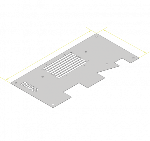
The maximum processable dimensions are 2000×2500 mm, but we can also evaluatesolutions for larger sizes. Make your request by sharing your project and sending us an RFQ!
Was this helpful? Make your quote now
Bends
Bend radius
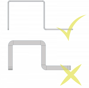
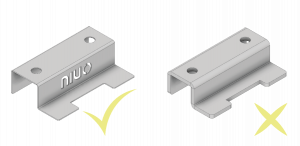
The bending radius must always be set according to the thickness of the sheet metal – with a radius smaller than the thickness, sheet metal production is impossible. Generally, therefore, the internal bending radius must be equal to the thickness of the sheet metal.
It is always advisable to consult the bending tables.
Short edge
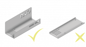
The bend edge must have a minimum length, because if it is too short, the bend is unfeasible. It is therefore necessary to take this aspect into account.
Given t the thickness of the sheet, the minimum dimensions of the edge b are generally calculated as:
B=4*T+2mm
It is always advisable to consult the bending tables.
Variable edge
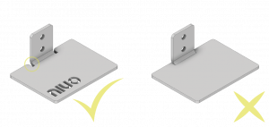
In bend edges that have variable length, the minimum bend edge size condition must be met by the shortest edge in the bend. Otherwise, unwanted deformation may occur during bending.
It is always advisable to consult the bending tables.
Consecutive bends
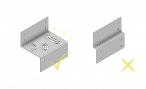
Even when there are consecutive bends, attention must be paid to the minimum size of the bend edge, as otherwise bending would not be feasible.
It is always recommended to consult the folding table.
Folding table
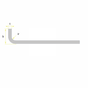
| t | 1 | 1,5 | 2 | 3 | 4 | 5 |
|---|---|---|---|---|---|---|
| b | 6 | 8 | 10 | 14 | 18 | 22 |
| Ir | 1 | 2 | 2 | 3 | 4 | 5 |
As the thickness of the sheet metal varies, there will be different minimum values for internal radius and edge length.
Folding support
Was this helpful? Make your quote now
Drilling and cutting
Position of holes and cuts
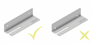
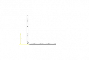
Holes and cuts near bends are not recommended. They may deform undesirably. To avoid this situation, simply place the holes or cuts at a distance greater than or equal to the minimum recommended distance for the edge.
Diameter of holes
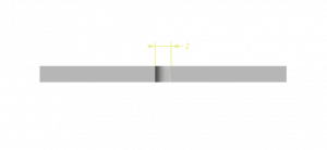
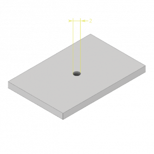
The diameter of the holes must be greater than or equal to the thickness of the sheet metal.
Hole Spacing
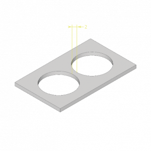
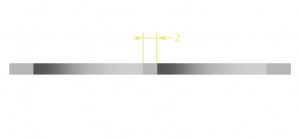
The distance between the holes must be greater than or equal to the thickness of the metal sheet.
Threading and countersinking
To have threaded or countersunk holes in your project, simply indicate the latter in the additional files that can be attached at the time of the request or in the notes.
Regarding the THREAD, in the 3D models there must be guide holes in correspondence with each threaded hole but not the threads. You can consult the table below for dimensional references in relation to the type of thread. In addition, a file with the information relating to the thread must be attached.
The realization of any threads must in any case be evaluated on the basis of the specific project requested.
Threading and countersinking table
| Fillet | M3 | M4 | M5 | M6 | M8 | M10 | M12 | M14 | M16 |
|---|---|---|---|---|---|---|---|---|---|
| Bore diameter Ø | 2.5 | 3.3 | 4.2 | 5.0 | 6.8 | 8.5 | 10.2 | 12.6 | 14.0 |
Similarly, for SHAZING in 3D models, the main hole must be present but not the chamfers.
Perpendicular Cutting
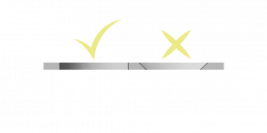
The cuts in the files must always and exclusively be perpendicular to the plane of the sheet metal.
Engraving of characters and logos

Was this helpful? Make your quote now
Production tolerances
The general tolerances observed for sheet metal processing are ISO 2768 – v.
The table shows some tolerance references related to thickness.
| Thickness (mm) | Fold tolerance (mm +/-) | Cutting tolerance (mm +/-) |
|---|---|---|
| 1 | 0,5 | 0,5 |
| 1,5 | 0,6 | 0,6 |
| 2 | 0,7 | 0,5 |
| 3 | 1,00 | 0,5 |
| 4 | 1,5 | 0,5 |
| 5 | 1,6 | 0,5 |
Was this helpful? Make your quote now
What files can I insert?
You can use CAD files in different formats, but the recommended one is the STEP format. In addition, you can upload additional files that are necessary and support the project in various formats (PDF, DWG, DXF and others)
Was this helpful? Make your quote now
File Organization
Tolerances in another document
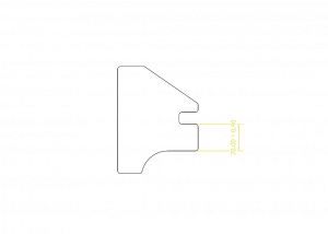
Tolerances must be indicated in a separately attached PDF document.
Features
Any specification regarding the treatment of the surface of the sheet metal must be placed in the comments section.
One drawing, one part

A single drawing must be contained in a single file. Therefore, avoid multiple parts in a single file.
Tidy design
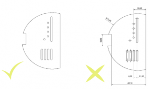
Only the cutting lines must be present in the final file. Therefore, do not specify tolerances, dimensions, construction or bending lines.
Cutoff views
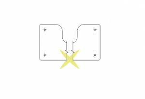
Avoid interrupt views or sections: the software will not recognize the sheet metal in its entirety.
Open or broken lines

Was this helpful? Make your quote now